ISO 17025 UKAS accredited
Over three decades of experience
Pitting Corrosion
Description
This is a highly localised form of corrosion attack whereby the metal surface is attacked at specific points by a corrosive medium, normally a liquid, leaving surface-breaking cavities. Attack can occur at surface features or defects, for example at mechanical damage, or microstructural phases, and defects such as voids or inclusions, and in a chemically degrading (corrosive) environment.
Pits are typically characterised by a small opening at the surface, enlarging in diameter and depth into the material.
Pitting attack is generally relatively slow at the initiation stage, but the rate of attack can increase significantly as the pit grows due to a variation in the electrical potential between the pit surface and the remainder of the original and unaffected surface of the metal. The amount of material lost from the metal is relatively small, but clearly highly localised. The overall strength of the component may be unaffected to any significant degree, but the localised penetration can cause rapid perforation of pipes and thin-walled vessels and the subsequent issues that could follow e.g. loss in pressure or product.
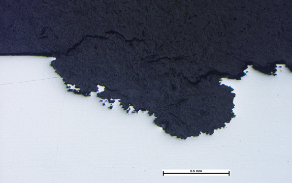
Photomicrograph of a section through a shallow pit in an austenitic stainless steel.
Mechanism
For the surface of a metal to resist ongoing corrosion, ideally a passive layer (typically an oxide) forms, which subsequently resists further oxidation or corrosion, or at least reduces it to a small and/or ‘acceptable’ level with respect to service performance and life. However, if a small area on the surface is affected by damage or chemical attack/degradation and is depassivated (i.e. is no longer passive), it becomes anodic to the remainder of the surface, which is cathodic. This anode-cathode couple forms an electrical circuit at a micro-scale with the flow of electrons from the anode to the cathode through the metal with a corresponding release of positively charged metal ions into the electrolyte (liquid) from the anode (pit). The release of these metal ions is the effective loss in metal from the pit which causes it to grow.
The energy in this electrical circuit is increased with the relatively small area of anode compared to the large cathodic area. This drives the pitting process and as the pit size increases, the rate of growth also increases. The metal ions in the electrolyte are then attracted to the cathodic area and are redeposited in some form (dependant on the metal and electrolyte).
Inside the pit, reaction of the metal ions with hydrogen in water (H2O) can produce HCl (hydrochloric acid) which accelerates the corrosion process.
The positively charged metal ions released in the pit also attract any negative ions in the liquid environment, such as chlorides (Cl-), which are aggressive with respect to corrosion and this can drive the pitting process.
A classic example of pitting corrosion is that experienced by stainless steels in the presence of chloride ions. Stainless steels are considered ‘stainless’ or resistant to corrosion due to the content of the element chromium in the steel. Minimum levels of chromium for stainless steels are typically considered to be approximately 12%. The chromium in the steel reacts with oxygen in the air to form a thin but stable chromium-oxide layer which resists further oxidation (‘corrosion’). Chloride ions can destroy the oxide layer, initiating, and then driving pitting corrosion.
Appearance
The appearance of a surface affected by pitting corrosion can vary significantly depending on the material and environment. A pit is by its nature, surface-breaking, but the size of the hole at the surface may be particularly small. The form of the sub-surface pit can vary with;
- Approximately hemispherical shape, with the size observed at the surface being representative of the general size of the sub-surface pit,
- Long ‘fingers’ or tunnels penetrating the material,
- Cavities that undercut and extend just beneath the surface of the metal.
The surface of the metal at the location of the pit may not exhibit any significant indication of its presence and then may go unnoticed; this may often occur during routine corrosion tests such as that defined in ASTM G48A, and pits are identified on the test coupon by running a metal probe across the surface. A thin and visibly unaffected ‘foil-like’ layer of metal may be all that is covering the pit which will readily collapse with light pressure from the probe.
More typically, the metal ions that exit the pit are carried by the liquid electrolyte and deposited on the (cathodic) surface as stains. On a vertical surface, the direction of the staining can lead back to the point of origin, the pit. In cases where flow of the liquid is slow or stagnant, the metals ions leaving the pit can redeposit on the surface immediately surrounding the pit orifice resulting in mounds or ‘pustules’.
Avoiding Pitting Corrosion
The occurrence of pitting in service may be down to several factors;
- Selection of a material with poor resistance to pitting corrosion,
- Incorrect heat treatment of a material normally resistant to pitting leading to microstructures prone to attack,
- Designer or user unaware of the potential for the material to be subjected to pitting,
- Changes to the operating environment such as a dry atmosphere becoming wet through condensation, contamination, or deposition of particulates,
- Microvoids in the material (such as may be expected in castings) which act as pre-existing pit-like defects rapidly promoting the concentration of damaging species in the void and subsequent pitting corrosion attack,
- Surface damage which may be mechanical or thermal. It is therefore vital to identify the cause of the pitting to then be able to take mitigating action.
Examples
Example 1: Heat treatment
Super duplex stainless steels used in corrosive environments in the oil and gas industry rely on their corrosion resistance on the development of the correct microstructure, consisting of delta ferrite and austenite. Due to the complex composition of the metal, incorrect heat treatments can lead to the development of additional phases or intermetallics such as sigma or Laves phases. These can significantly affect the local composition of the material at a micro-scale rendering such areas susceptible to pitting corrosion attack. Examination of sections of the material under the metallurgical microscope and corrosion testing such as that defined in ASTM G48A readily identifies such phases.
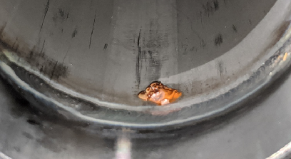
Example 2: Environment
In the drive for more sustainable power generation, anaerobic digesters are becoming more commonplace to produce biogas. The main vessel of the digester had been specified by the designer as a 316 stainless steel; a material not uncommon for such uses. However, the digester vessel wall was subjected to significant pitting attack which had occurred within a few months of entering service. The feedstock for the digester was highly variable in its content and so the environment within the vessel could not be predicted within acceptable limits. The corrosion attack had occurred at the liquid-vapour interface, a location that exhibits constant changes in exposure to vapours, gases, liquids, and solids. In view of this highly variable environment, selection of a material with a higher resistance to corrosion, and pitting in particular, such as 6MO/S31254 was considered. Ideally, proof of the change in material would require testing, but the operator of the equipment investigated the use of epoxy resin coatings to isolate the vessel wall from the biomass instead. A further consideration may have been not to use ‘stainless steel’, but a non-corrosion resistant carbon steel, again with an internal coating of epoxy or glass.
Example 3: Environment

The fittings also exhibited remnants of heavy scale which would be expected in a ‘normal’ environment. This scale develops naturally, following installation, with the rate of development slowing with time, and the scale then protects the underlying metal from further attack if the conditions of the water remain constant. The presence of this scale indicated that at installation, the conditions were indeed normal, but in time, these changed to one where the water became corrosive leading to the observed pitting. The client was then able to focus their attention on investigating the control and monitoring procedures used on the hot water system to avoid recurrence.
Example 4: Environment
A 316 stainless steel pipework system was installed in a facility handling various soaps and cleaning agents. Extensive pipework systems had been manufactured on site by a welding contractor. A few weeks after installation and commissioning one of the systems started to show multiple leaks through ‘pin holes’ in the pipe walls and particularly in the vicinity of welds; none of the other systems were affected even though the materials and welding practices were the same. The affected system however, had been exposed to a different commissioning procedure using towns water, and product, with a short period of stagnation.
Investigation identified pitting corrosion that had developed on the inside of the pipework. Pustules of corrosion deposits were observed to be associated with heat tints developed at weld heat affected zones, in a manner consistent with microbial action (see white paper on microbial induced corrosion (MIC)). However, although the initiator was microbial activity, the process of pitting corrosion followed the same mechanism as any other pitting corrosion.
Example 5: Manufacturing
Small spots of corrosion were observed on stainless steel panels soon after installation on a building. Investigation using scanning electron microscopy with analysis using the x-ray fluorescence facility on the SEM (EDS) identified small globules and particulates of ferrous-based material, and which differed from the panel material. The form and composition of the particulates were typical of ferrous grinding debris. A review of the manufacturing facility identified that stainless steel panels were regularly worked on in the same area as carbon steel structural steels. Processes in the facility included welding and grinding, and it was apparent that grinding debris could impact on other materials in the area.
Grinding or machining of low alloy steels in the same location as stainless steels is particularly problematic. Particles of grinding debris from the low alloy steel can fuse or ‘stick’ to the stainless steel surface. These particulates can readily corrode, changing the local environment at the surface of the stainless steel, which then also corrodes by pitting, which is what had occurred on this occasion.
If caught early, and if the material is thick enough such as on a heavy-duty casting rather than a thin-walled pipe, it may be possible to grind out the damage to prevent continued pitting attack. However, it must be ensured that all remnants of pits have been removed otherwise any remnants of the pits could then continue to corrode once in service.
Inspection of the panels on the building revealed a clear difference between those that were affected and unaffected by corrosion. They had been exposed to weathering for a sufficient period of time to reveal those that exhibited ferrous debris, and so on this occasion, rather than trying to dress out areas of corrosion it was considered that replacement of the affected panels only was more economical.
